Motorisation of the model is now
quite advanced. All 15 of the crawler units have had their motors and gearboxes
installed. The gearing in each consists
of 5 steps of reduction, all done with my large-tooth steel gears using
pinion/gearwheel clusters bolted together with 3mm bolts and nuts and brass
spacers between, as explained in an earlier blog-post, so that large torque
transfers are possible. The first 3
shafts are 4mm rods, the latter 3 shafts being 8mm, since torque increases as
one goes done the line of reduction steps.
The final drive to the 4½ inch nylon wheels was explained earlier.
 |
| Crawler gearbox from below |
 |
| Benchtesting a main crawler unit |
 |
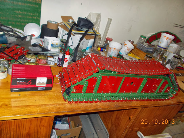
| All 12 main crawler belts installed on crawlers |
The crawler belts have now been
assembled and fitted. This presented
quite some challenge as my original idea of bolting the treads together with
locknutted bolts through holes drilled larger than 4.2mm did not work
smoothly. I had hoped to obtain bolts
which were threaded only part way along in order to facilitate the movement
through the holes as the belt flexed.
Unfortunately I could only get fully-threaded bolts which tended to jam
up. I therefore had to revert to the
tried and trusted method of bolting 1 inch girder cleats to the treads and then
locknutting fishplates to the cleats.
This meant an extra 3,600 parts needed to be made, with many more nuts and
bolts for the locknutting. I also needed
to increase friction between the nylon wheels and the steel crawler
treads. This was done by attaching a
small piece of 1.5mm insertion rubber to the inside of every tread. The attachment was done using a high-performance
rubberising adhesive called Sikaflex 221 as well as two 12mm bolts with
locknuts for safety (locknutting to prevent squashing the rubber inserts on
tightening).
The result is a smoothly-running
belt which develops immense breakout force. (The more vertical load applied the
more horizontal force results, according to the well know law of frictional
force versus normal reaction) Each of the main crawlers happily carries my
weight (85Kg) – this is about what is expected from each when finally assembled. All 12 of the main crawlers have now been
assembled as seen in the photograph.
The 3 small crawlers for the
auxiliary unit have also been completed.
These have been fitted and the complete unit tested. Again, it happily
carries my weight which is about what is expected of this auxiliary unit. (Note
that the wheel/gearing specifications of the smaller crawlers are the same as
for the main crawlers – it is only the frame size which is smaller. Hence, all 15 will travel at the same speed.
 |
| Crawlers installed on auxiliary unit |
 |
| Another view of auxiliary unit |
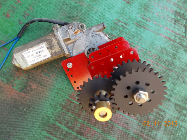
Shown in the accompanying
photograph are 4 motor/gearbox units which will be used to slew the upper arms
of the machine. Each employs 6 steps of
reduction. The final gear (48 large
toothed) is attached via an aluminium spacer to a 4 inch aluminium wheel as
seen. These wheels will have teeth cut
into them to mesh with the large ring gear created using 8mm bolts protruding
outwards on a heavy steel strap. I will
leave this operation until the gearboxes have been fitted and I can see the
final position taken up.
 |
| A slewing motor gearbox |
 |
| All 4 slewing motor gearboxes |
The 4 inch aluminium gear takes 100
seconds per rotation. This will give a
complete slewing time of about 20 minutes.
Although this is a low angular speed the linear speed at which the
bucket wheel passes will be reasonable, since the latter sits 16 feet out from
the vertical axis of rotation of the machine.
Another set of motor/gearbox units
is the set of 3 steering gearboxes shown here.
 |
| A steering thruster unit |
 |
| All 3 steering thruster units |
These drive 12mm threaded rods into
small aluminium blocks attached to the crawler frame bridge supports on their steering
tillers (and tapped out to 12mm holes).
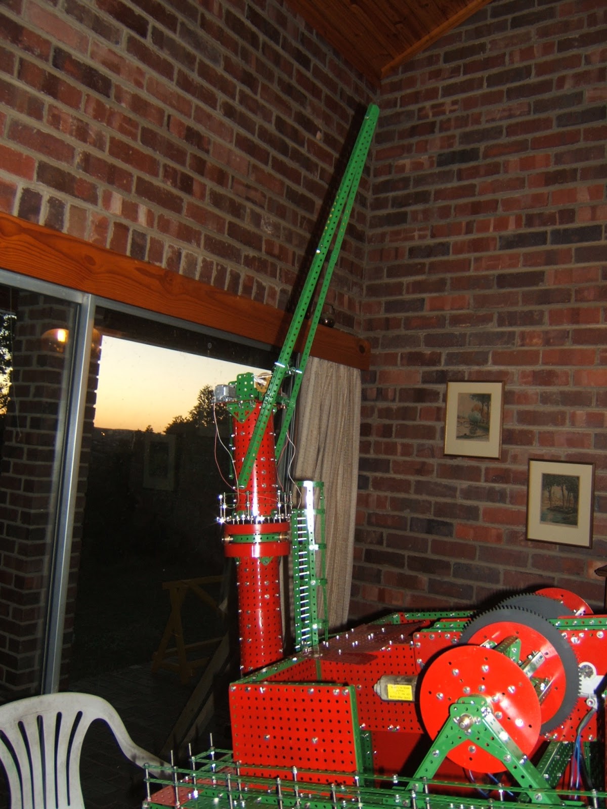
Shown next are the 4 inch aluminium
pulleys at the tops of the 2 upright arms.
These were all cut from an aluminium log 102mm diameter, 1.2m long. My 455mm abrasive cut-off machine was not up
to the job but my friend Dixie Westcott came to the rescue and cut the log into
40 slices on his industrial bandsaw for me. This took 3 days, with numerous
breaks to allow the bandsaw to cool!
 |
| Some of the 34 pulleys in the upright arms |
The day is approaching when I will
have to assemble a team of 8 people to help me lift the central unit onto its
crawler system. Shown in the picture
here is the wooden cradle I will bolt onto the top of the central unit.
 |
| Wooden lifting cradle |
Below are shown 2 correct-height
trestles on which to rest the cradle which the crawler system is completed.
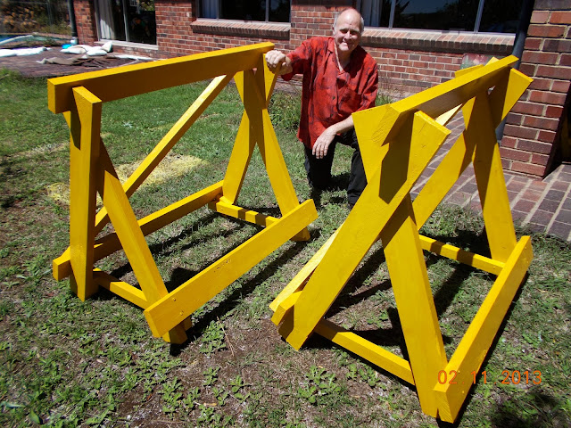 |
| Main unit working trestles |
In the next picture are some
components of two 9 foot high scaffolds I will need to set the upright arms in
place (one on either side for safety).
Once the cables are in place on the aluminium pulleys the 2 winding
drums can be started up so that the machine can at last support itself.
 |
| Components of a 9 foot scaffold |
A fairly major still to be done is
the installation of about 2 kilometres of electrical wiring (including a 10
metre main harness connecting machine to control box. This will have 110 cores,
2 per motor and 2 for lights).
| Final delivery arm positioning winch |


