I am indebted to a number of people and organisations for help in
manufacturing parts and for information about the bucket wheel
excavator.
The steel plate and girders and strip blanks
were cut with great precision by Steelcut Services (Pty) Ltd. of Port Elizabeth,
using their CNC laser cutting machine, and the girders received a bend
(90, 135 or 110 degrees as required). A big thank you to Roger, Sally and Werner at Steelcut for their patience.
All fixers (screws, nuts, blots, threaded rod) were supplied by Mr. Screw of Port Elizabeth. Thank you to Roxy for her knowledge and efficiency.
Information on the machine was obtained initially from the Web but when the going got difficult I was given great encouragement, technical information and some wonderful pictures by Thyssen Krupp Materials Handling of Johannesburg. Thank you to Managing Director Klaus-Peter Mueller for his warm reception and encouragement.
Thanks are also due to Derek of K.V. Precision Engineering of Uitenhage, Eastern Cape, for making some high precision drilling jigs which enabled me to drill the equivalent of 1 kilometer through mild steel (equivalent to 1,000,000 holes in 1mm gauge steel!).
I am also grateful to all the 'bucket wheel excavator friends' who have watched progress enthusiastically over the last years, and trust they will hang in there till the end! Finally I thank my wife, Eileen, for her extreme forbearance and tolerance in agreeing that the model be assembled in the lounge of our home!
Sunday 27 January 2013
Thursday 24 January 2013
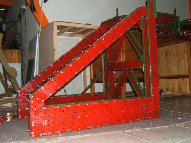
The vertical arms
Both vertical arms have been constructed, the longer being 9 feet long and is shown below:
 |
| Vertical arm Visible in the above picture are the bearing boxes for 16 four inch diameter aluminium pulleys which allow the main bucket-wheel arm to be raised and lowered by cables onto 2 winding drums at the far end of the counter-balance arm (which has yet to be built). |
 | ||
| Bearing box for aluminium pulleys at top of vertical arm |
 |
| The 2 vertical arms can be clearly seen to the right of the bucket-wheel |
The auxiliary unit
I have also started the auxiliary unit which supports the other end of the long off-loader arm. This is carried on three smaller crawler units whose frames can be seen in the shots below:
Also visible in the above pictures is the final off-loader cross slider which incorporates another conveyor belt. This is about 6 feet long. This is the point where coal is finally offloaded from the machine onto the ground-based conveyor belts to the power station.
The cross slider conveyor belt is also driven by a window-winder motor (seen on right in above shot).
The support to all fifteen of the crawler frames is provided by 20mm stainless steel rods. These can be discerned in the auxiliary unit case by looking at the second shot above - in the middle of the crawler.
 |
| Auxiliary unit with final cross-slider |
 |
| View of crawler frame support to auxiliary unit |
 |
| Motor-driven roller on the cross sliding unit |
The support to all fifteen of the crawler frames is provided by 20mm stainless steel rods. These can be discerned in the auxiliary unit case by looking at the second shot above - in the middle of the crawler.
Crawler units
Parallel with the previously described I built the frames of the 12 main crawler units, largely out of 2mm gauge plate because of the huge load that will eventually rest on them. The 3 bridge-like support structures which pivot on the underside of the toroidal core via the 20mm high-tensile bolts (which go into the 3 fin-like appendages to the core - described earlier) were also constructed. These support structures are immensely strong, each consisting of 8 adjoined closed boxes made entirely from 2mm plates. Each must support about 350 kgs.
Steering tillers can be seen in the top picture. These will be attached to motor-driven ram units to effect steering of the machine.
 |
| Twelve crawler frames plus supporting structures |
 |
| Four crawler frames with supporting structure |
Wednesday 23 January 2013
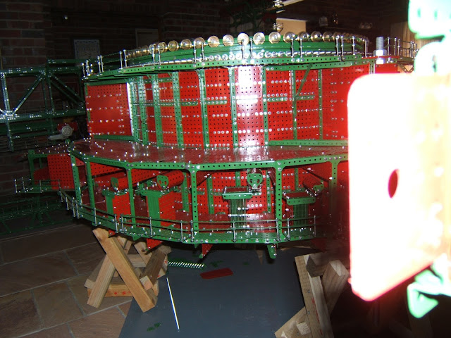
Central unit construction
 |
| Main machine pivoting structure |
The very strong triangular central frame which bolts onto the turntable ring followed:
 |
| Central arm support |
The sides of the box girders shown above are created entirely out of two mm. gauge steel plates as this unit will support over 400 kgs.
Then came the central barrel-like structure which supports the whole weight of the upper rotating machine arms. This was created out of 32 bulkheads with girder frames and fully plated with 1mm gauge plate. These measured 40 holes by 16 holes each. The outer skin was created by overlapping 0.6mm gauge plates to give an overall skin thickness of 1.2mm. A very high screw-density was used so that the unit was a close to weld-strength as possible. The upper and lower annular faces were created using 32 eleven by seven hole plates as was the matching turntable ring show above.
The roller race between the above units was created from 65 solid brass train wheels based on Meccano's 1.125 inch-diameter wheel but wider, and with deeper flanges. This roller race will carry a live weight of about 450 kgs.
An initial attempt at fabricating (from Meccano strips) the rails on which the wheels run was not very successful. The motion was too jerky. I replaced this by a single strip of 25x3 mm mild steel, needing only one join. The action is now much smoother and the rails stronger.
 |
| Roller race |


At this stage the barrel-like toroidal structure was placed on trestles and the three supporting projections were created out of 2mm gauge plates. Each of these carries a 20 mm diameter high-tensile threaded rod. These rods pass down into three bridge-like structures which carry the 12 main crawler units.

Also attached to the outside of the toroidal main frame are the outer features of this unit, such as, the electric substation with 5 transformers, the large box-like structure at the front and the personnel control room at the rear.
 |
| Electrical sub-station |
 | |
| Main supporting bolt |
 | |
| Receiving conveyor in main unit |
 |
| Personnel access stairs |
 |
| Another view of personnel stairs |

 |
| Conveyor belt exiting main body |
 |
| Control Room |
 |
| Cantilever arm |
 |
| A transformer |
 |
| Cantilever arm |
Off-loader arm
The next section to be constructed was the long off-loader arm which worked out to be nearly 19 feet long.
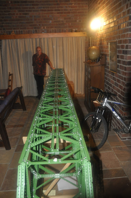 As you will note from the above shot Bagger sections are now residing in the lounge of our home - more on this at a later stage!
Therre are two conveyor belts on this section. The first is attached to the arm itself and goes to the halfway mark, approximately. This conveyor offloads onto a second one which is carried in another frame which rides on brass train wheel (20 in total) on the underside of the main arm.
The below shot shows the positioning of 4 of the wheels:
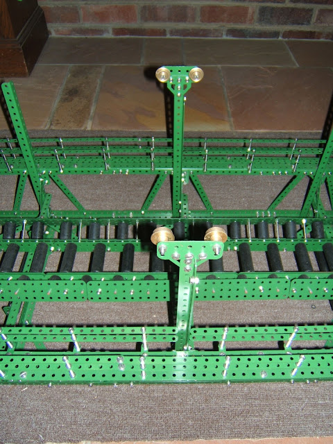 The above arrangement allows the distance between the main unit of the machine and the auxiliary unit (see photo of prototype) to be varied by a telescoping action.


Therre are two conveyor belts on this section. The first is attached to the arm itself and goes to the halfway mark, approximately. This conveyor offloads onto a second one which is carried in another frame which rides on brass train wheel (20 in total) on the underside of the main arm.
The below shot shows the positioning of 4 of the wheels:


Motive power
Motive power is provided by a series of automotive window winder motors which I obtained at a very reasonable price as a factory surplus.
At each end of the conveyor belts there is a 6 inch wide aluminium roller driven by a window winder motor, with adaptive gears made for the purpose:
 The bucket wheel frame also incorporates two driver's cab assemblies which can be raised and lowered in two 'lift shaft' appendages at the sides. These cab assemblies are only 2kgs each and can be driven up and down by Meccano's little 6 volt plastic utility motors, driving small winches.
At each end of the conveyor belts there is a 6 inch wide aluminium roller driven by a window winder motor, with adaptive gears made for the purpose:

Building starts
 |
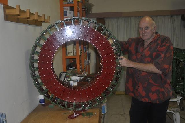
| Bucket-wheel arm |

The wheel has a diamter of 42 inches and has 19 buckets attached. The German prototype has 18, but as things worked out 19 gave me a convenient closed circle of plates, as you can see in the pictures:


At the centre of the frame is a conveyor belt, with a wide U-section created by putting 3 small rollers abreast. The rollers were cut from 3/4 inch meranti dowels with stub axles epoxied in at each side. There are over 1000 rollers in the whole model:


Tuesday 22 January 2013
Start of the Bagger 288 project
In mid 2009 I was facing retirement from my position as a Mathematics lecturer at Rhodes University in Grahamstown, South Africa, after being in this trade for 40 years. I decided to pull out my old Meccano set and to look for a suitable project to tackle.
My initial thought was to build the battleship Bismarck, something I had wanted to do since seeing the pictures of this sunken ship taken by Roger Ballard and his team when they found her, at some 15,000 feet depth in 1989.
As my set was woefully short on plates I started making replica plates to enable me to build an 18 foot Bismarck. I also started purchasing 4mm stainless steel machine screws and nuts as replacements for the 5/32 inch Meccano ones, as I would need many more than my set held.
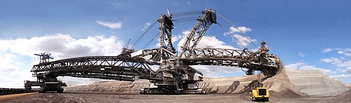
By June 2010 I began to reconsider the Bismarck project, as a Meccano ship was not all that exciting from a mechanisation point of view. I vaguely remembered an excavator which I had seen somewhere which worked in coal mines in Germany. On 'Googling' the machine I decided it was what I wanted to build! There were many mechanical features which could be brought to life using electric motors. The machine is known as Bagger 288, an example of a bucket wheel excavator built by Krupp of Germany and powered electrically by Siemens Electrical, also of Germany.
.JPG) Bagger 288 is a 240,000 cubic metre per day capacity excavator, weighing over 14,500 tons. It mines lignite coal in an open cast situation, placing the material onto ground-based conveyor belts which carry it directly to the power station.
Bagger 288 is a 240,000 cubic metre per day capacity excavator, weighing over 14,500 tons. It mines lignite coal in an open cast situation, placing the material onto ground-based conveyor belts which carry it directly to the power station.
I settled eventually on a scale which gave my proposed model an overall length of about 41 feet (if one includes a 16 foot section of ground-based conveyor this is a 57 feet total length) and height of about 16 feet. A vast number of replica parts (plates, strips, girders, brass train wheels, collars, rollers, gears and pulleys) were needed and I decided to make as many as possible myself. This, over the months since starting the model, has probably taken more time than the actual building!
My initial thought was to build the battleship Bismarck, something I had wanted to do since seeing the pictures of this sunken ship taken by Roger Ballard and his team when they found her, at some 15,000 feet depth in 1989.
As my set was woefully short on plates I started making replica plates to enable me to build an 18 foot Bismarck. I also started purchasing 4mm stainless steel machine screws and nuts as replacements for the 5/32 inch Meccano ones, as I would need many more than my set held.
By June 2010 I began to reconsider the Bismarck project, as a Meccano ship was not all that exciting from a mechanisation point of view. I vaguely remembered an excavator which I had seen somewhere which worked in coal mines in Germany. On 'Googling' the machine I decided it was what I wanted to build! There were many mechanical features which could be brought to life using electric motors. The machine is known as Bagger 288, an example of a bucket wheel excavator built by Krupp of Germany and powered electrically by Siemens Electrical, also of Germany.
.JPG)
I settled eventually on a scale which gave my proposed model an overall length of about 41 feet (if one includes a 16 foot section of ground-based conveyor this is a 57 feet total length) and height of about 16 feet. A vast number of replica parts (plates, strips, girders, brass train wheels, collars, rollers, gears and pulleys) were needed and I decided to make as many as possible myself. This, over the months since starting the model, has probably taken more time than the actual building!
Subscribe to:
Posts (Atom)